Bluetooth controlled car using Arduino
Welcome to the blog of SR Automation & Robotics,
I have written this blog on how to make a Bluetooth control car using arduino, L298N motor driver, and bo motors. The code for this is also written in this blog. Please like our facebook page and sign up to our website. link given below.
Feel free to contact us for any type of advanced automation and robotics projects.
PARTS and MATERIALS:
- Arduino Uno
- L298 Motor Controller
- HC-05 Bluetooth Module
- 2 Wheel Drive Robot Chassis
- Male to Female Connectosr
- 9 Volts Battery
- Android Phone
- Double Sided Tape
- Velcro
WIRING DIAGRAM:
You can refer to the attached Wiring Diagram file for quick and easy guide on wiring connections
PROCEDURE:
STEP 1:
Assemble the Motor and Chassis.

STEP 2:
Attach the Arduino board to the chassis. You can use Double Sided tape.
STEP 3:
Attach the L298 Motor Controller Module into the chassis. You can use double sided tape.
STEP 4:
Attach the Bluetooth module into the chassis using double sided tape.
STEP 5:
Attach the 9V battery to the chassis. You can use velcro so you can easily detach it when you need to recharge the battery
STEP 6:
Connect the motor terminals to the L298 module motor channels. The left motor wheel should be connected to the Motor channel A and the right motor wheel should be connected to the Motor channel B of the L298 board. There might be cases that you will interchange the Red and Black wire of the motor connection to the motor module that will cause reverse motor rotation when you finished uploading the code but you can refer to the attached image for the wiring connection. Just swap the black and red wire connection if turns in a different direction

STEP 7:
Get the male to female connector to connect the four (4) INT of the L298 module to the digital pins of Arduino Board. Connect the female pin to INT1, INT2, INT3 & INT4 of the L298 module while the male pin from the other end should be connected to Pin 5,6,10 & 11 port of the Arduino board respectively.
STEP 8:
Get the three male to female connector to connect Bluetooth to the Arduino board. Connect the female pin to the TXD, VCC and GND of the Bluetooth module while the male pin from the other end should be connected to the RX, 5V and GND of the Arduino board respectively. Refer to the attached wiring diagram for reference.

STEP 9:
The Arduino board needs voltage supply and we can use the external power source of the L298 module to supply power to the Arduino board. In this tutorial I used 9V battery to supply the L298 module which will be connected to the VMS and GND. Connect the wire from the VMS and GND to the Vin and GND of the Arduino board respectively.
STEP 11:
We will be needing an android phone and download the apps in the google to control the car via Bluetooth. Go to the Playstore and search for Arduino Bluetooth RC Car apps. Download the apps and install it in your android phone.
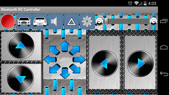
Connect the 9V battery supply to the VMS and GND of L298 module. Open the Bluetooth RC Car apps in your phone and go to Settings to connect to the car. It will scan for the available Bluetooth and once it find the HC-05, select it. It might prompt for a pin code for the first time and just enter 1234. Once Bluetooth was paired, you can now drive your Car using your android phone. That is all and enjoy the ride!!!

Code of the above project:-
-----------------------------------------------------------************************----------------------------------------------------------
//This program is used to control a robot using a app that communicates with Arduino through a bluetooth module.//Error Code Chart: Code 01; Turnradius is higher than Speed; Code 02; Speed is higher than 255;
#define in1 5 //L298n Motor Driver pins.
#define in2 6
#define in3 10
#define in4 11
#define LED 13
int command; //Int to store app command state.
int Speed = 230; // 0 - 255.
int Speedsec;
int buttonState = 0;
int lastButtonState = 0;
int Turnradius = 0; //Set the radius of a turn, 0 - 255 Note:the robot will malfunction if this is higher than int Speed.
int brakeTime = 45;
int brkonoff = 1; //1 for the electronic braking system, 0 for normal.
void setup() {
pinMode(in1, OUTPUT);
pinMode(in2, OUTPUT);
pinMode(in3, OUTPUT);
pinMode(in4, OUTPUT);
pinMode(LED, OUTPUT); //Set the LED pin.
Serial.begin(9600); //Set the baud rate to your Bluetooth module.
}
void loop() {
if (Serial.available() > 0) {
command = Serial.read();
Stop(); //Initialize with motors stoped.
switch (command) {
case 'F':
forward();
break;
case 'B':
back();
break;
case 'L':
left();
break;
case 'R':
right();
break;
case 'G':
forwardleft();
break;
case 'I':
forwardright();
break;
case 'H':
backleft();
break;
case 'J':
backright();
break;
case '0':
Speed = 100;
break;
case '1':
Speed = 140;
break;
case '2':
Speed = 153;
break;
case '3':
Speed = 165;
break;
case '4':
Speed = 178;
break;
case '5':
Speed = 191;
break;
case '6':
Speed = 204;
break;
case '7':
Speed = 216;
break;
case '8':
Speed = 229;
break;
case '9':
Speed = 242;
break;
case 'q':
Speed = 255;
break;
}
Speedsec = Turnradius;
if (brkonoff == 1) {
brakeOn();
} else {
brakeOff();
}
}
}
void forward() {
analogWrite(in1, Speed);
analogWrite(in3, Speed);
}
void back() {
analogWrite(in2, Speed);
analogWrite(in4, Speed);
}
void left() {
analogWrite(in3, Speed);
analogWrite(in2, Speed);
}
void right() {
analogWrite(in4, Speed);
analogWrite(in1, Speed);
}
void forwardleft() {
analogWrite(in1, Speedsec);
analogWrite(in3, Speed);
}
void forwardright() {
analogWrite(in1, Speed);
analogWrite(in3, Speedsec);
}
void backright() {
analogWrite(in2, Speed);
analogWrite(in4, Speedsec);
}
void backleft() {
analogWrite(in2, Speedsec);
analogWrite(in4, Speed);
}
void Stop() {
analogWrite(in1, 0);
analogWrite(in2, 0);
analogWrite(in3, 0);
analogWrite(in4, 0);
}
void brakeOn() {
//Here's the future use: an electronic braking system!
// read the pushbutton input pin:
buttonState = command;
// compare the buttonState to its previous state
if (buttonState != lastButtonState) {
// if the state has changed, increment the counter
if (buttonState == 'S') {
if (lastButtonState != buttonState) {
digitalWrite(in1, HIGH);
digitalWrite(in2, HIGH);
digitalWrite(in3, HIGH);
digitalWrite(in4, HIGH);
delay(brakeTime);
Stop();
}
}
// save the current state as the last state,
//for next time through the loop
lastButtonState = buttonState;
}
}
void brakeOff() {
}
----------------------------------------------*****************************************----------------------------------------------------
Thank You for investing your precious time, hope you got what you needed.
Have a good day!!!
SR Automation and Robotics
Ravi S. Sharma
+91 7487801107
ravi84739@gmail.com
Visit us at: SR Automation & Robotics
follow us on facebook @ srautomationrobotics
Feel free to contact us for any type of automation and robotics projects and for workshops.
SR Automation and Robotics
Ravi S. Sharma
+91 7487801107
ravi84739@gmail.com
Visit us at: SR Automation & Robotics
follow us on facebook @ srautomationrobotics
Feel free to contact us for any type of automation and robotics projects and for workshops.

Comments
Post a Comment